Description of a process activating turning table as an external kinematics for KUKA robots. Flowing instruction below you will be able to control external kinematic.
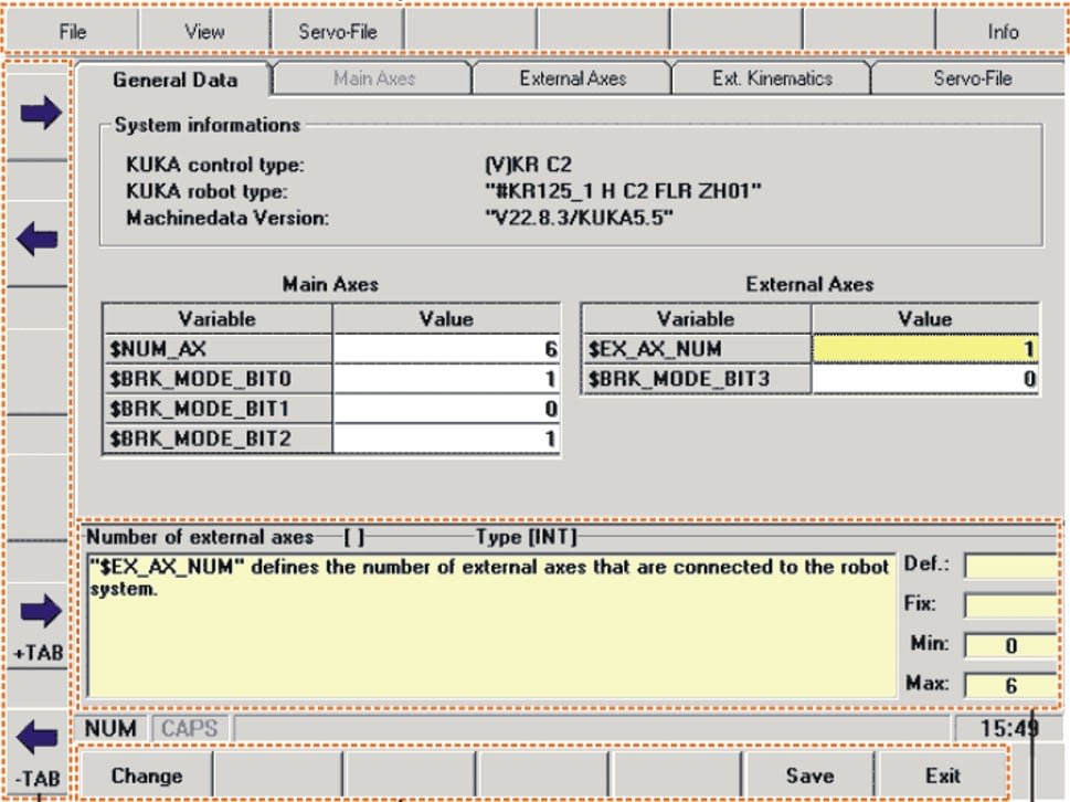
1. Go to menu SETUP > SERVICE > AXISCONFIGURATOR
2. Change the variable $EX_AX_NUM ( number of external axis ) set 1 or 2 (depending on number of external axis) and save configuration.
3. Switch to the tab EXTERNAL AXIS – parameters of external axis
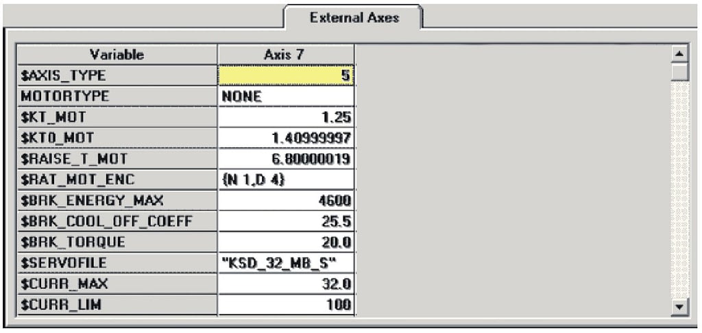
4. Set a values regarding list below
$AXIS_TYPE[7]=5 ;type of external axis
$KT_MOT[7]=1.43700004
$KT0_MOT[7]=1.58000004
$RAISE_T_MOT[7]=6.80000019
$RAT_MOT_ENC[7]={N 1,D 4}
$BRK_ENERGY_MAX[7]=7377
$BRK_COOL_OFF_COEFF[7]=41.0
$BRK_TORQUE[7]=33.0
$SERVOFILE7[]=”KSD_32_MI1ALL” ***
$CURR_MAX[7]=48.0
$CURR_LIM[7]=100
$CURR_MON[7]=17.5
$CURR_CAL[7]=1.0
$CURR_COM_EX[7]=100.0
$DSECHANNEL[7]=7
$PMCHANNEL[7]=21
$AXIS_RESO[7]=4096
$IN_POS_MA[7]=0.100000001
$RED_VEL_AXC[7]=10
$RED_ACC_AXC[7]=10
$RED_ACC_OV[7]=100
$VEL_AXIS_MA[7]=3350.0
$G_VEL_PTP[7]=35.0
$G_VEL_CP[7]=75.0
$I_VEL_PTP[7]=500.0
$I_VEL_CP[7]=200.0
$LG_PTP[7]=0.753
$LG_CP[7]=0.800000012
$G_COE_CUR[7]=15
$APO_DIS_PTP[7]=90.0
$SOFTN_END[7]=-10000
$SOFTP_END[7]=-10000
$RAT_MOT_AX[7]={N -4446,D 19} ***
$AX_ENERGY_MAX[7]=3042
$MAMES[7]=0.0
$VEL_AX_JUS[7]=0.25
$L_EMT_MAX[7]=9.60000038
$RAISE_TIME[7]=830.0
$RED_ACC_EMX[7]=230
$DECEL_MB[7]=414.5
$AXIS_DIR[7]=1
$EX_AX_ASYNC[7]=0
$ACYNC_EX_DECOUPLE[7]=0
$JERK_MA[7]=1000
$AXIS_JERK[7]=8.0284996
*** value depends on version of motor, driver and reduction gearbox
5. Switch to the tab EXT. KINEMATICS and set the values as on the pictures below
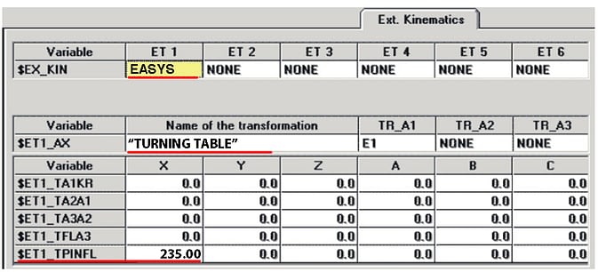
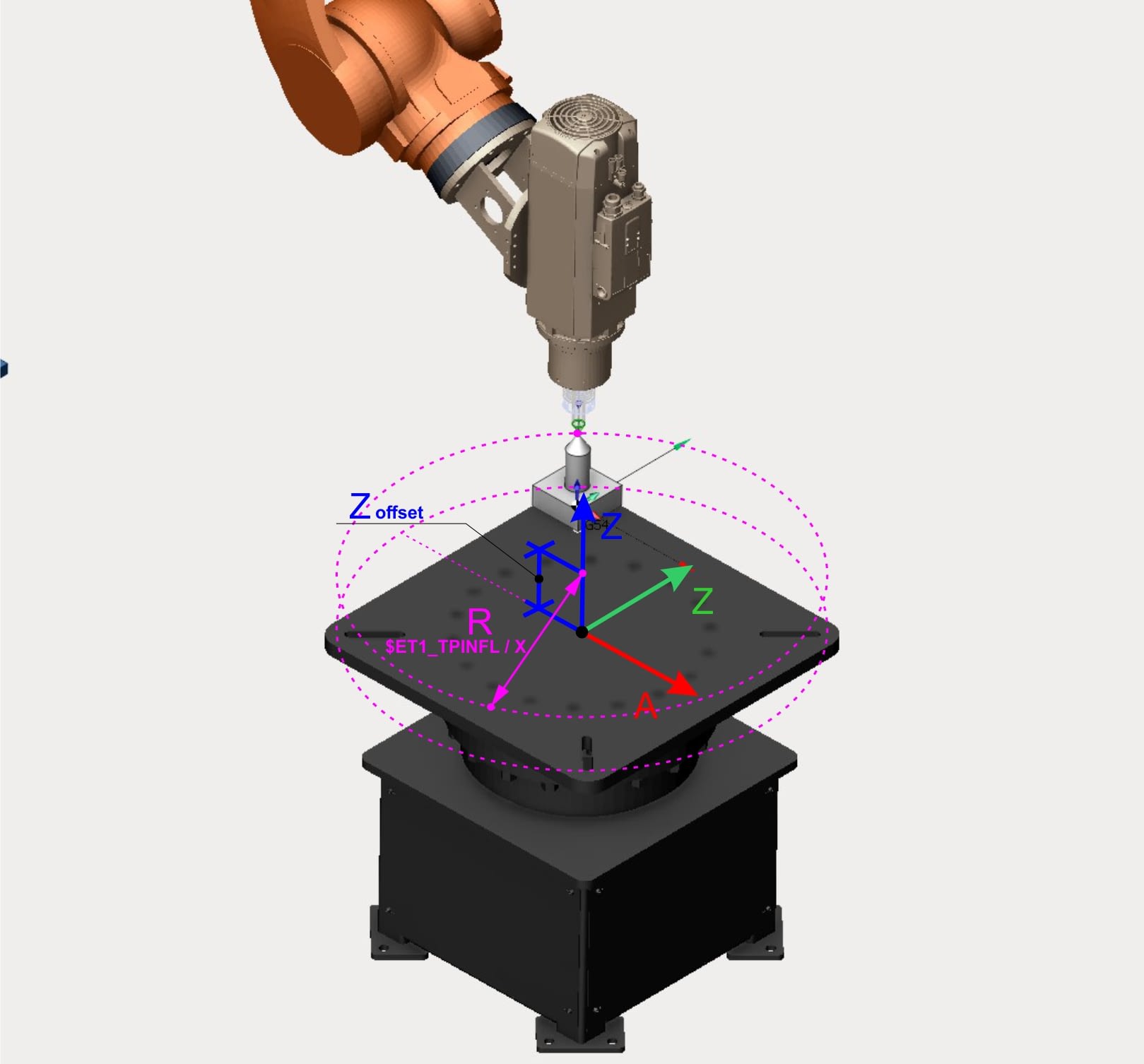
6. Set distance from the center of the table to reference point in the filed
$ET1_TPINFL / X = distance from the center of table to reference point.
R value on the picture
7. Save all parameters and make a cold boot of the system
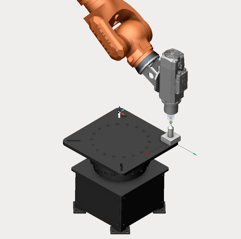
8. After rebooting make a test, move the turning table.
Make a simle program for testing ratio of rotting table and execute it.
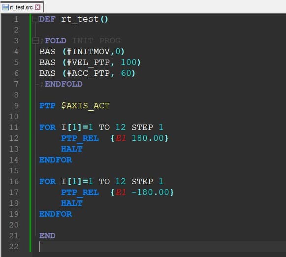
Open the monitor of current axis position before moving table. Match the TCP and some sharp reference on the table,
Execute the test programa and check if the TCP amd referenc onthe table match after rotting 360 degrees.
If it doesn’t match then change the value of $RAT_MOT_AX[7] . If you don’t know what value you should put there contact with support and get proper value.
After checking and adjusting setting move to the next step of calubrating a root point.
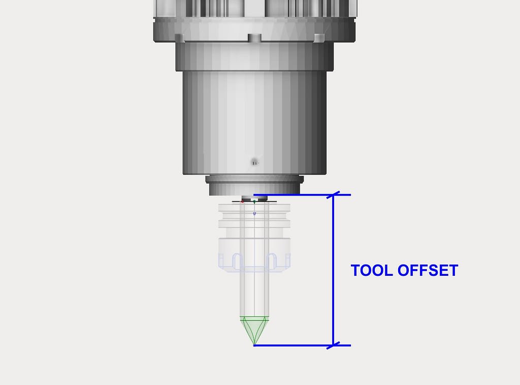
9. Prepare a sharp tools for measuring root point of turning table.
Use any sharp TCP
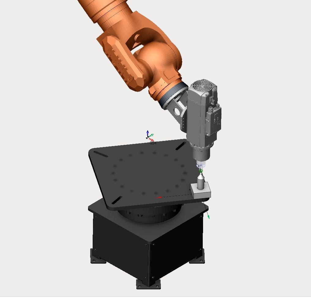
8. Call an internal procedure in the menu SETUP > MEASURE > EXTERNAL KINEMATIC > ROOT POINT and follow the instruction during measuring the root point.
9. Match TCP and reference on the table . Press the button MEASURE and press NEXT.
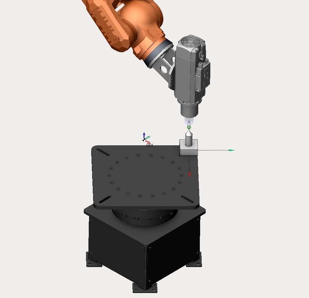
10. Rotate the table approximately for 45 degree and then move TCP to the reference point. Press the button MEASURE again and then press NEXT
11. Rotate table again and then move TCP to the reference point. Press the button MEASURE again and then press NEXT
12. This is the last point you have to measure. Rotate table again and then move TCP to the reference point. Press the button MEASURE again and then press NEXT
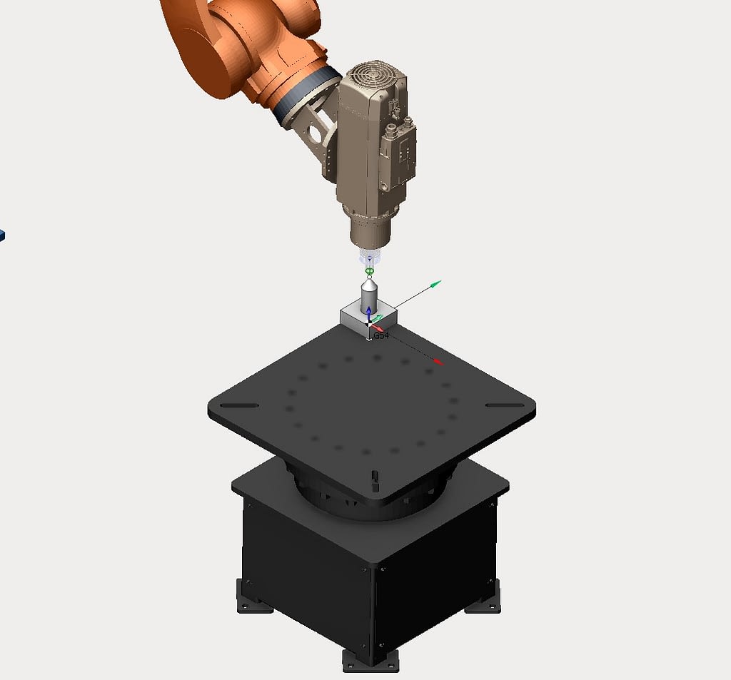
13. After measuring 4 points you’ll get a data of your root point . Press the button SAVE to storage the data of root point.
The data will be stored into CONFIG.DAT variable is MACHINE_DEF [N-nuber of the external axis + 1].ROOT

14. To get a real data of root point you need to update it by removing a distance from the reference to the rotating table flange.
Call menu MONITOR > VARIABLE > SINGLE and type a name of variable MACHINE_DEF [ N-number of the external axis + 1 ].ROOT and press enter
An example of a variable of the reference Z-offset – FRAME R_OFFEST { X 0.0, Y 0.0 ,Z -110.54, A 0.0, B 0.0, C 0.0 }
In the filed NEW VALUE set MACHINE_DEF [ N-number of the external axis + 1 ].ROOT : R_OFFEST